Most Commented
CADopia Pro 23 v22.3.1.4100 (x64)


Description material
File Size: 306 MB
CADopia is a powerful Computer-Aided-Design software for engineers, architects, designers and drafters virtually anyone who creates, edits, or views professional drawings. CADopia 19 is available in 12 languages – Chinese, Czech, English, French, German, Italian, Japanese, Korean, Polish, Portuguese, Russian, and Spanish.
CADopia Professional Services can help you maximize the returns on your investment in CAD technology. CADopia provides upfront consulting services, custom application development, staff training,technical support, and project outsourcing solutions.
Digital Signature
A digital signature helps organizations sustain proof of the signer's identity, intent, and the integrity of electronic documents. It guarantees that a file has not changed since the file was signed. Once you digitally sign a drawing, it becomes a Read-only file that cannot be tampered, giving you the security that you need for some applications.
Layer Manager Palette and Dialog
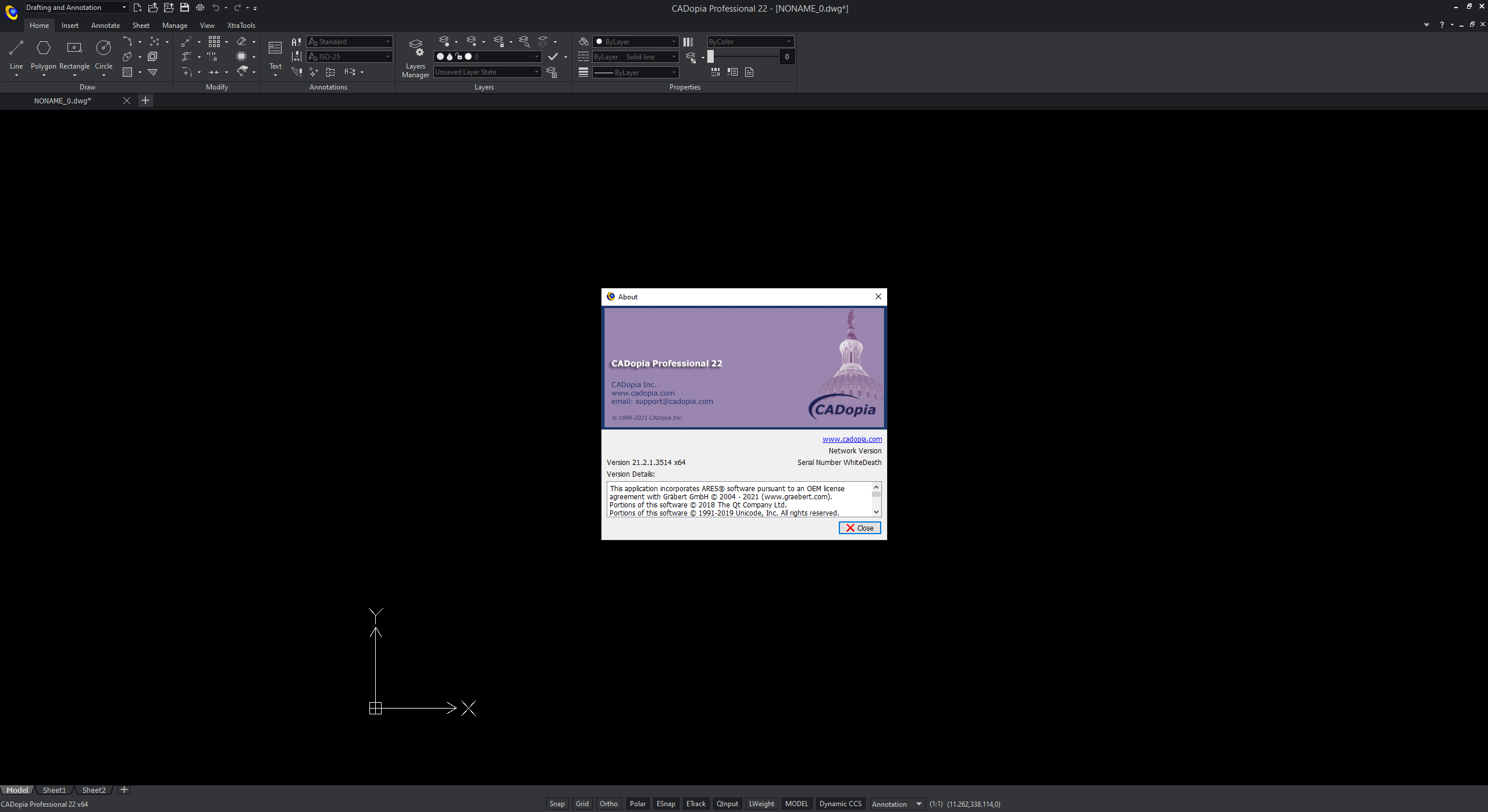
CADopia has a new dark user interface, but you have the option to switch between the dark user interface and the white user interface by picking Switch UI Style from the Windows menu or typing _UISTYLE on the command line. The UI Style change takes place when you restart the application. You can also switch between ribbon and classic interfaces.
Merge Layers
The command MergeLayer, also available from the new Layer Manager, assists you in merging the content of selected layers into another one. For example, you can use it when you receive a drawing from a vendor and want to simplify the layers as per the requirements of your project.
Chamfer edges of solids
Chamfer Edges works in 3D similarly as for the Chamfer command you use in 2D. It creates a sloped transition between two surfaces or adjacent faces on a 3D solid which distance can be customized. Alternatively, you can also round an edge with the command FilletEdges.
PolySolid
With PolySolid you can create 3D walls with constant height and width just like you draw polylines. Segments can, therefore, be straight or curved. PolySolids can be created by selecting points. Alternatively, you can convert existing 2D entities such as polylines, arcs or lines into 3D PolySolid entities.
New User Interface
CADopia has a new dark user interface, but you have the option to switch between the dark user interface and the white user interface by picking Switch UI Style from the Windows menu or typing _UISTYLE on the command line. The UI Style change takes place when you restart the application. You can also switch between ribbon and classic interfaces.
Redefine Base Point of a Block
Change the base point of a block in your drawing, without exploding it. The new REDEFINEBASEPOINT command allows you to set a new base point for blocks. The new base point applies to the selected block and any previous insertion of the block get the new base point. This eliminates the steps of exploding and recreating the block before replacing it.
2D Spiral and 3D Helix
Create 2D spirals and 3D helices. The HELIX is a new entity that can be used in 2D to create spirals or in 3D to create helices. You may further use an HELIX as an extrusion path and create complex shapes such as bolt threads, circular stairs or ramps.
Modify 3D solid primitives
New grip points in 3D solid primitives allow you to edit the dimensions of the solid directly. You may also use Quick Input to input a new value. Alternatively, you may change the shape by editing the values in the properties palette for the selected primitive.
Dynamic Custom Coordinate System (CCS)
Enable the Dynamic CCS to automatically align the coordinate system to the face you are editing. The Dynamic CCS can be turned on or off from a toggle in the bottom of the User Interface or by pressing F6. When enabled the CCS gets aligned to the surface automatically as you move over it.
Edit block attribute properties
The new Block Attributes Manager lets you redefine the attributes definitions of a block intuitively. You may define the visibility of an attribute, change the order, default values and other parameters, directly from a comprehensive dialog box.
Formulas in tables & export to Excel
Use formulas in tables from within your drawings and improve workflows with Microsoft Excel® using import from/export to Excel feature. Insert formulas such as the sum or average of a column or equations. Copy a table from Excel or use the new EXPORTTABLE command to export a table in your drawing to a .CSV file.
Import PDF and convert to DWG
Now, you can import a PDF file into CADopia Professional Edition 2016 and save it as a DWG format file, effectively allowing you to convert a PDF drawing into an editable .DWG format file.
Power Trim
Trim or extend entities faster than with any other CAD Software. Trim multiple entities in once by simply moving your mouse around and describing a path with your mouse. CADopia will trim the entities while you move the mouse.
Quick Modify
Draw and modify much faster by combining these frequently used commands. Use only one command to perform and combine multiple actions on a same selection of entities: Move, Rotate, Scale and/or Copy without leaving the command.
Standard DWG file format.
-CADopia's native file format is DWG, which allows you to open AutoCAD drawings.
-DWG read and write support upto AutoCAD version 2015.
-Allows Import and export of PDF File (Professional version only).
Advanced 3D functionality.
-CADopia uses the ACIS solid modeling engine to provide you most advanced 3D modeling tools.
-Supports features such as lofting, sweeping along a path, extrusion and revolution for creating complex, mathematically complete 3D models suitable for downstream engineering analysis and manufacturing.
System Requirements
OS:Microsoft Windows 10, 8, 2008 server(32 bit and 64 bit).
CPU:Intel® Core™ 2 Duo or better (recommended).
Memory:4 GB or higher recommended.
Space:1 GB of free hard-disk space for installation.
GPU:High Color (16 bit) graphics card (3D graphics accelerator card recommended).
Display:1024 x 768 screen resolution.
Screen :
What's New
HOMEPAGE
https://cadopia.com/
Buy Premium Account From My Download Links & Get Fastest Speed.

Join to our telegram Group
Information
Users of Guests are not allowed to comment this publication.
Users of Guests are not allowed to comment this publication.
Choose Site Language
Recommended news
Commented


![eM Client Pro 9.2.1735 Multilingual [Updated]](https://pikky.net/medium/wXgc.png)



![Movavi Video Editor 24.0.2.0 Multilingual [ Updated]](https://pikky.net/medium/qhrc.png)

