Most Commented
Simulating Dc-Dc Converters With Qspice


Description material

Simulating Dc-Dc Converters With Qspice
Published 10/2024
MP4 | Video: h264, 1920x1080 | Audio: AAC, 44.1 KHz
Language: English | Size: 5.35 GB | Duration: 10h 1m
Learn the operation of basic non-isolated dc-dc converters through QSPICE simulations
What you'll learn
Operating principles of basic dc-dc converters
Non-isolated converters - buck, boost, buck-boost, Cuk, SEPIC, ZETA converters
Beginner QSPICE tutorial
Using QSPICE to simulate dc-dc converters
Analysis of simulation results to understand converter operation
Using 3rd party SPICE models in simulations
Requirements
Basic electrical engineering
Description
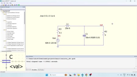
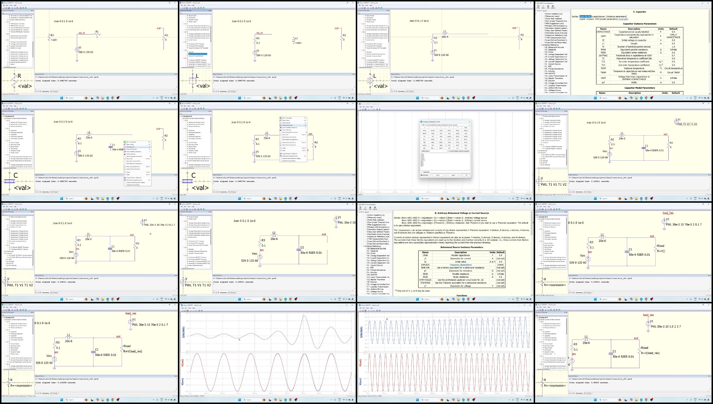
This course will describe how to simulate power electronic circuits with QSPICE. QSPICE is the latest trending SPICE software by Qorvo and is the successor to LTspice by Analog Devices. QSPICE is projected to be widely adopted by the power electronics and analog electronics industry. This course is targeted towards beginners who have never used a SPICE software before, and will use QSPICE to simulate basic dc-dc converters that any undergraduate will study in introductory course on power electronics. In addition to demonstrating the use of QSPICE as a simulation software, the course will examine a number of non-isolated dc-dc converters in great detail, such as the buck, boost, buck-boost, Ćuk, SEPIC and ZETA converters.The course will describe how QSPICE can be used to analyse the operation of a dc-dc converter, and therefore, can be used as both an effective learning tool for students, as well as a teaching tool for educators. The course will describe how QSPICE can be used to include hardware details in a simulation by importing third-party SPICE models provided by manufacturers, to bring simulations closer to a hardware prototype. The course will describe in detail the operation of the some of the more complex dc-dc converters such as the SEPIC and the ZETA converters, by using basic network laws and the basic principle of exchange of energy.QSPICE is a completely free simulation software based on SPICE which has been used for several decades. QSPICE features many exciting improvements over other SPICE software such as the ability to write control code using C++ or Verilog, and greater ability to simulate non-linear components. These features make QSPICE a very powerful tool for a power electronics engineer both in industry and academia.
Overview
Section 1: Introduction
Lecture 1 Welcome to the course
Lecture 2 Target students of the course
Lecture 3 Requirements of the course
Lecture 4 Tips on completing the course
Section 2: Installing and using QSPICE
Lecture 5 Introduction
Lecture 6 Background and history of SPICE
Lecture 7 Downloading and installing QSPICE
Lecture 8 A quick tour of QSPICE
Lecture 9 Links and references
Lecture 10 Starting with simulation - importance of ground and SPICE directives
Lecture 11 Generating plots
Lecture 12 Sine voltage source
Lecture 13 Pulse voltage source
Lecture 14 Piece-wise linear voltage source
Lecture 15 Correction on PWL voltage source parameters
Lecture 16 R-L-C circuit with behavioural resistor component
Lecture 17 Plot commands as SPICE directives
Lecture 18 Correction to simulation
Lecture 19 Conclusions
Section 3: Buck converter
Lecture 20 Introduction
Lecture 21 Converter topology
Lecture 22 Operation of the buck converter
Lecture 23 Drawing skeletal circuit in schematic editor
Lecture 24 Understanding parameters of the diode and the switch
Lecture 25 Running the simulation with switch and pulsed voltage waveform as gate pulses
Lecture 26 Analysing simulation results with switch and pulse gate voltage waveform
Lecture 27 Writing C++ code for implementing PWM logic
Lecture 28 Simulation results with the C++ PWM implementation
Lecture 29 Adding a MOSFET to the converter
Lecture 30 Running the simulation with the MOSFET
Lecture 31 Handling the Windows antivirus blocker
Lecture 32 Handling simulation transients due to initial conditions
Lecture 33 Ending remarks on the simulation
Lecture 34 Conclusions
Section 4: Boost converter
Lecture 35 Introduction
Lecture 36 Topology and operation of the boost converter
Lecture 37 Creating the boost converter simulation
Lecture 38 Analysing the simulation results of the boost converter
Lecture 39 The importance of handling initial conditions
Lecture 40 Conclusions
Section 5: Buck-boost converter
Lecture 41 Introduction
Lecture 42 Topology and working of the buck-boost converter
Lecture 43 Setting up the simulation of the buck-boost converter
Lecture 44 Analysing the simulation results of the buck-boost converter
Lecture 45 Handling initial conditions
Lecture 46 Conclusions
Section 6: Cuk converter
Lecture 47 Introduction
Lecture 48 Topology and operation of the converter
Lecture 49 Setting up the simulation of the Cuk converter
Lecture 50 Analysis of the simulation results
Lecture 51 Conclusions
Section 7: Single-Ended Primary Inductor Converter (SEPIC)
Lecture 52 Introduction
Lecture 53 Topology and operation of the SEPIC
Lecture 54 Setting up the SEPIC simulation
Lecture 55 Analysis of SEPIC simulation
Lecture 56 Conclusions
Section 8: ZETA converter
Lecture 57 Introduction
Lecture 58 Topology and operation of the ZETA converter
Lecture 59 Simulation of the ZETA converter
Lecture 60 Analysis of simulation results
Lecture 61 Conclusions
Section 9: Third-party models and hardware details
Lecture 62 Motivation for including hardware details
Lecture 63 Creating sub-circuits with hierarchical entries
Lecture 64 Choosing a gate driver for the MOSFET in the simulation
Lecture 65 Downloading and importing the gate driver SPICE model
Lecture 66 Making connections to gate driver SPICE model - part 1
Lecture 67 Making connections to gate driver SPICE model - part 2
Lecture 68 Correcting gate driver connections to prevent under-voltage lockout (UVLO)
Lecture 69 Conclusions
Section 10: Conclusions
Lecture 70 Conclusions
Electrical engineering students,Junior engineers in the power industry,Test/automation engineers

Download
Fikper
https://fikper.com/fi3q1YREnx/Simulating.dcdc.converters.with.QSPICE.part1.rar.html
https://fikper.com/CAkmHBtqRj/Simulating.dcdc.converters.with.QSPICE.part2.rar.html
https://fikper.com/HnSplKx9an/Simulating.dcdc.converters.with.QSPICE.part3.rar.html
RapidGator
https://rapidgator.net/file/a3a4f0ebbd631e5de4dde5df9af88106/Simulating.dcdc.converters.with.QSPICE.part1.rar
https://rapidgator.net/file/4653d501399f23831dd60407613e5dd7/Simulating.dcdc.converters.with.QSPICE.part2.rar
https://rapidgator.net/file/593e761826804661eb93d99ac8749328/Simulating.dcdc.converters.with.QSPICE.part3.rar
FileStore
TurboBit
https://turbobit.net/9lhu83g93r8l/Simulating.dcdc.converters.with.QSPICE.part1.rar.html
https://turbobit.net/dmtfldf6ny4i/Simulating.dcdc.converters.with.QSPICE.part2.rar.html
https://turbobit.net/6k5rk22e5pl7/Simulating.dcdc.converters.with.QSPICE.part3.rar.html
Join to our telegram Group
Information
Users of Guests are not allowed to comment this publication.
Users of Guests are not allowed to comment this publication.
Choose Site Language
Recommended news
Commented


![eM Client Pro 9.2.1735 Multilingual [Updated]](https://pikky.net/medium/wXgc.png)


![[PORTABLE] AVAide DVD Ripper 1.0.12 (x64) Multilingual](https://i.postimg.cc/WpZKVHLf/AVAide-DVD-Ripper.png)
![Movavi Video Editor 24.0.2.0 Multilingual [ Updated]](https://pikky.net/medium/qhrc.png)

